LOFTING - A HOW-TO GUIDE

For our January Technical Meeting we were lucky enough to be addressed by Glen Swarbrick, whose Swarbrick and Swarbrick Yachts at Henderson we've visited on two previous occasions. This time he was good enough to come to us and explain plan lofting - a subject which seems to bemuse some would-be builders.

As Glen explained, lofting is a necessary precursor to building a boat from many older plans. Modern computer plans are usually accurate enough to work from immediately, as are older plans which have a full Table of Offsets and claim "No Lofting Needed". A table of offsets, incidentally, is a tabular set of numbers which describe the location of all important parts of the hull, measured from the waterline (or a baseline) and from the centreline, at all the vertical frame stations. Unfortunately most older TOO's will be in Imperial measurements, using, say, inches, eighths and thirty seconds (or something similar); thus 10, 5, 3 would mean 10 inches, 5 eighths and 3 thirty seconds - messy, no? If you're lucky they could be in decimals of an inch or better still, metric. A TOO and "No lofting needed" means you can go ahead and draw up your frame shapes full size from this and start building.

However, lofting may be unavoidable. This is the process of expanding the original plans to FULL SIZE - that's right; a 20' boat needs a 20' plan. Why? Because small errors on the original, possibly 1/10 full size, plan are going to be much bigger when you build it.

Now, what it's all about - the curves of the actual boat. No colours here, just lead pencil which you can erase and adjust (which you'll do often). Mark the position of the keel line (or at least the centre of the canoe body of the hull) at all the frame stations and attempt to join these points up in a fair curve using battens and nails. Already some adjustment may be needed to accommodate all the points. Having drawn a pencil line around the batten, repeat the process for the sheer line (or deck edge), only this will have to appear twice, once on the sheer plan and once on the waterline plan. Incidentally, Glen warned against measuring the same distance twice or more. Measure once and on later occasions mark off the original distance on a "tick stick" or step it out with large dividers if you have them. That way you avoid two different measurements of the same distance.

Now you can start to draw out some, but not all, of the cross-sections. Start with the midships one and one from close to each end - three in all. You'll probably need thinner battens to accommodate the curves here. These can appear at their actual stations, say, two, five and eight (most plans number their stations from the bow and there are usually ten, plus zero for the bow itself. After this it's the long slog of replicating all the buttock lines and waterlines. Remember, buttock lines represent vertical slices through the hull, parallel to the centreline - waterlines are horizontal slices. Once you're happy with the buttocks and waterlines you can probably use them to draw out the remaining crosssections (one, three, four, etc) but you'll more than likely end up referring to the original plan as well. When you do you'll find discrepancies, and end up erasing and adjusting lines a fair bit; but the more you do now, the more accurate your building frame will be.

Every pencil line of 0.3mm will expand to 3mm wide for a start! Which side of that 3mm do you build to?

So, Glen said, the first step is to acquire a lofting board, which, itself should be a few feet longer than the boat because the curves will eventually be traced around long battens and often the battens have to be constrained beyond the boat to get the right curve.

Medium Density Fibreboard (MDF) in about 6mm should do for this although of course you'll have to join sheets. The board is usually operated on the floor but it might go vertically on a wall or up on several school desks when your editor did it. It needs to be painted a light colour, preferably white, with anything cheap you can get your hands on - undercoats are fine. A selection of battens not necessarily 20' long, but 8 or 10 is nice, cut from ply or similar, straight edges (aluminium extrusions are good) and a large square are all needed. To locate the battens in their curves on the MDF at various times we use thin nails or panel pins, 1" or 1!" long, so you need them and a claw hammer (or pincers).

Having got all that together, we can start drawing, building up from the original plan and the TOO, if it's available. Although Glen didn't say so, I think it's common to save space at this stage by overlapping the sheer plan (side elevation) and the waterline plan (the view from above), with the body plan (the all-important frame sections) appearing in the middle. Unfortunately this will lead to a confusing collection of grid lines and Glen's suggestion to mark them in two or three different colours makes sense. Fine fibre-tip pens would be the shot for this. You could mark all your waterlines on the sheerplan in one colour, buttock lines on the waterline plan in another and the frame stations for both in a third. Incidentally, the horizontal waterlines may be measured either from a baseline below the hull or up and down from the Load Water Line.

At this stage your bodyplan (the crosssections) can all appear together in the middle of the sheerplan. Two or three diagonals can be drawn on the bodyplan (just use the ones on the original) and the lengths to where the diagonal crosses the skin can be marked at the appropriate station. Once again, join up the points and you should get a fair curve; if not start adjusting again. The diagonals, as Glen said, are excellent for checking the fairness of the bilge areas. After this, practical building points can be incorporated, including keel width, rabbet line, stem shape, true transom shape, etc.

After this (and it took your editor about three weeks part time to get this far when he lofted up his own design) you're ready to start the building frame, probably by transferring the cross sections to 9 or 12mm particle board (but don't forget to remove the thickness of the skin and any interior framing before cutting out). How to transfer the shapes? Well, don't start measuring all over again, anyway. Glen favours the flat-head nail method. Place a goodly number of flat-head nails, lying down, around the curve in question, with the edges of the heads on the curve. Lower the piece of particle board which will become the frame over these gently, and rap it all round with a mallet. Lift off and the curve should appear as small indentations from the nail heads. Join up with pencil before cutting out with jigsaw or bandsaw. Of course, this will give you only one half of the frame; you're back to measuring to get the other half. Alternatively, you could do an intermediate stage, firstly drawing one half on 4mm ply or MDF, cutting it out and using the template to trace both sides of the building frame. If you start with the largest frame you can probably get several sections from the one piece.

Glen had a few hints and tips on building on a jig, but they're probably best left to a full report on that stage of building, but in the mean time we have to thank him for a very comprehensive description of the black, or at least dark, art of lofting. Much appreciated, thanks Glen.

A LABOUR OF LOVE, ON VALENTINE'S DAY

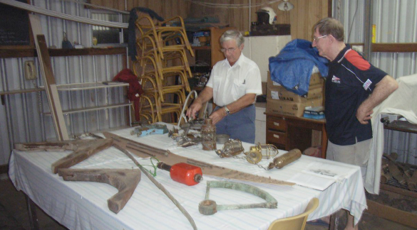
On Valentine's Day we made the pilgrimage to Ron Lindsay's workshop at Maraginiup, near Wanneroo to see his mammoth project. The love of his life is "Kiewa", a 1913-built Edwardian launch, springing from the hand of Ron's great-grandfather and his brother in Lawrence's boatyard at the foot of Mill St, Perth. (I said Fremantle in the last issue) Ron discovered her as a total wreck adjacent to the old Mews yard in Claremont. He salvaged her and kept her in storage for ten years. He's also restoring two vintage motorbikes on much the same sort of timescale!

The hull measures 40' by 10' beam. She seems to be fairly flat-bottomed with a firm turn of bilge so draft would be fairly shallow. She has a fairly plumb stem and an interesting cruiser stern following a long flat run aft over the propeller. Early photos show her as having a long, single-level cabin with an awning and exposed helming position at the stern. Ron anticipates some modernisation of this scheme to include a protecting wheelhouse. The photos also show a short mast up forward to which was rigged a basic lugsail to minimize rolling. I can remember this device on fishing boats in the '50s, but they were set at the stern, a much better system for steering in a cross-wind. All in all the design is described as "local" with an American influence. She was built for Dr. William Trethowan, the then-commodore of RPYC and she must have been the Queen of the fleet in her day.

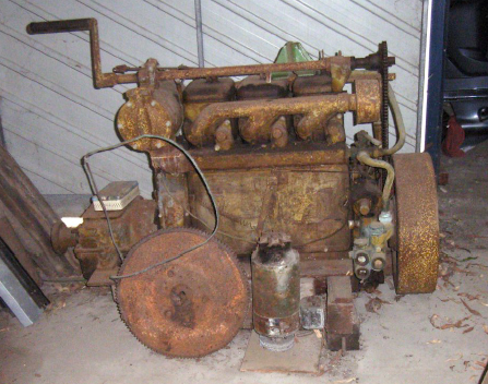
Kiewa appears to have had only two engines in her long life. The first was a three cylinder Ailsa Craig petrol, long since gone, and this was followed by a marinised three cylinder Lister diesel in about 1938, which Ron has. He's got a new Volvo turbo-diesel of about 70hp ready to go in. A century ago engines were weak and boats had to be clean-lined anyway, so this engine should have more than enough poke.

Some planks had to be discarded and Ron determined to replace these with the correct timber - a bit difficult since New Zealand will no longer export kauri. He eventually got his hands on 3/4ton of it and got it shipped here by means he wasn't prepared to enlarge on! The sound original planks had all shrunk excessively and so as each was removed it was splined to make it wider and reduce the caulking gaps to something reasonable before being refitted. It should be added that kauri would appear to be about the world's best planking timber, in terms of longevity and resistance to rot, followed closely by Huon pine.

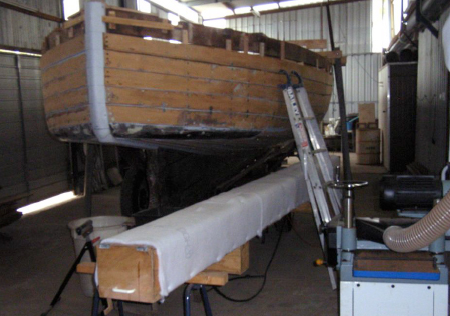
By August '08 the project was getting to be expensive and with the planking virtually complete Ron determined to bring her home to Maraginiup, which he did. That was a problem in itself, because although he has extensive shedding, the area best suited to the exercise was a lean-to beside the main workshop and it had insufficient headroom. So Kiewa spent a couple of months outside under tarpaulins while Ron rebuilt the lean-to more substantially with plenty of headroom. This guy is serious!

Now he's ready to start steaming and fitting new ribs from karri. An ingenious steam box stood beside the boat, ready. It's about 15' long, externally insulated, with the bottom removed in two places to allow the fitting up of a pair of small steam baths. Each bath has an industrial-strength electric element in it to turn water into steam. Plumbed in externally to this is a large-ish trough of water which automatically tops up the steam baths - neat!

But that all lies in the future; right now the challenge is to restore the hull and create a superstructure. The first step, in December '07, was to move the vessel to Steve Handley's boat building workshop in Fremantle, where Kevin Hart did the initial work. Kevin was on hand on Sunday and described the work done. The hull had kept its shape with most of the NZ Kauri planking being sound, although the ribs and floors were all shot. However it was sufficient to enclose her in an external frame for the move.

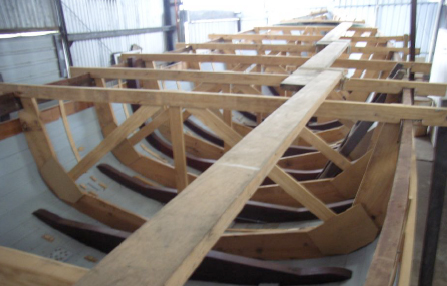
A full set of internal building frames was made up and installed, allowing the ribs and floors to be removed and discarded and these frames were still doing their job when we saw her. Kevin then dropped the keel, stem and sternpost out (sounds easy, doesn't it?), cleaned them up and added another 6" to the keel depth before refitting the whole assembly. He also added a keelson above, which hadn't existed before.

Ron is estimating about 40 minutes steaming for each rib, although he'll have several on the go at any time. Some will have to be laminated, due to the firm turn of the bilge referred to earlier. When two thirds of the ribs are in, the temporary frames can come out and the job completed. After that there's floors, engine beds, steering, deckbeams and decking, before fitting out and superstructure.

So you can see that although Kiewa has come a long way, and to a very high standard, there's still a long way to go and it looks like Ron's doing most of it himself from here on, so it's a big job. Still, with the family building connection, there's no way he's going to give up. We must thank him for his hospitality, including the afternoon tea so generously provided and wish him the best of luck in completing the project.

Peter Leggatt (l) examines original boat fittings with Ron Lindsay